

Fanuc Communication
Serial
| Signal Name | Pin # | I/O | Description |
| SD | 2 | O | Sending Data |
| RD | 3 | I | Recieving Data |
| RTS | 4 | O | Request To Send: This Signal is set to on when the NC starts sending data and is turned off when the transmission ends. |
| CTS | 5 | I | Clear To Send: When this signal and the DSR signal are set high, the NC can send data from SD. If this signal is set low the NC will stop sending data after two more characters are sent. Jump 5 to 4 if signal isn't used. |
| DSR | 6 | I | Data Set Ready: When the external device is ready to operate to needs to set this signal high. If this signal goes low anytime during data transfer, NC alarm 86 will occur. Jump 6 to 20 if signal isn't used. |
| SG | 7 | - | Signal Ground |
| CD | 8 | I | Carrier Detect: Signal must be straped to DTR. Jump 8 to 20 in cable. |
| DTR | 20 | O | Data Terminal Ready: This Signal is set to on when the NC is ready for operation. |
| FG | 1 | - | Frame Ground: This electrically connects the NC cabinet ground to your extirnal device's ground. Note: If grounds are of a different potential between devices, damage to equipment and/or electric shock can occure. Be sure all equipment is properly grounded! |
Timing Chart When The Fanuc NC Sends Data To External Device.
1. NC outputs DC2.
2. NC outputs punch data in succession.
3. When data processing is delayed by the external device, including the character currently being
sent if the CTS (CS) signal is turned off:
a) Data output stops within two characters including the currently transmitted character when
CTS (CS) signal is input to the NC. When CTS (CS) signal is turned on again, data transmission
starts. (Fig. A)
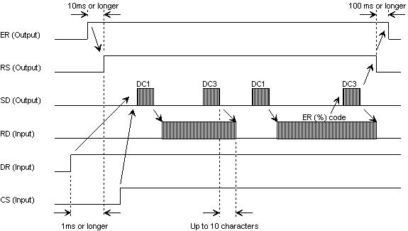
Timing Chart When The Fanuc NC Receives Data Into Memory.
1. NC outputs DC1.
2. The external device starts sending data upon receiving DC1.
3. The NC sends DC3 when the NC processing is delayed or input buffer is full.
4. The external device stops sending to the NC after receiving DC3. The external device can
send up to 10 characters after receiving DC3. If more than 10 characters are sent after the DC3
was sent alarm 87 will occur.
5. The NC sends DC3 after completing delayed processing and input buffer is empty.
6. The external device resumes sending data after receiving DC1.
7. NC sends DC3 upon completing data read
8. The external device stops sending data to NC.

b) If the control code DC3 is input to the NC, the NC will stop data output within ten
characters. When control code DC1 is input to the NC, the NC will start sending data
again. (Fig. B)
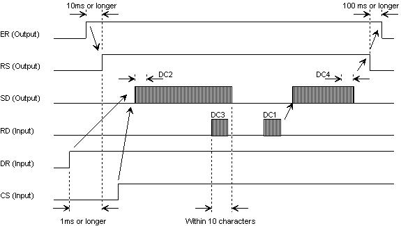
4. The NC starts sending the next data in the output buffer if the CS signal is turned on after
the external device completes data processing.
5. NC issues DC4 upon completing data output.
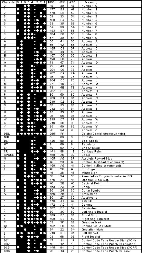
ISO Tape Code Chart
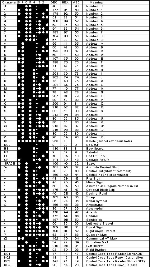
EIA Tape Code Chart

Cable Information


Fanuc Communication
Serial

| Signal Name | Pin # | I/O | Description |
| SD | 2 | O | Sending Data |
| RD | 3 | I | Recieving Data |
| RTS | 4 | O | Request To Send: This Signal is set to on when the NC starts sending data and is turned off when the transmission ends. |
| CTS | 5 | I | Clear To Send: When this signal and the DSR signal are set high, the NC can send data from SD. If this signal is set low the NC will stop sending data after two more characters are sent. Jump 5 to 4 if signal isn't used. |
| DSR | 6 | I | Data Set Ready: When the external device is ready to operate to needs to set this signal high. If this signal goes low anytime during data transfer, NC alarm 86 will occur. Jump 6 to 20 if signal isn't used. |
| SG | 7 | - | Signal Ground |
| CD | 8 | I | Carrier Detect: Signal must be straped to DTR. Jump 8 to 20 in cable. |
| DTR | 20 | O | Data Terminal Ready: This Signal is set to on when the NC is ready for operation. |
| FG | 1 | - | Frame Ground: This electrically connects the NC cabinet ground to your extirnal device's ground. Note: If grounds are of a different potential between devices, damage to equipment and/or electric shock can occure. Be sure all equipment is properly grounded! |

Timing Chart When The Fanuc NC Receives
Data Into Memory.
1. NC outputs DC1.
2. The external device starts sending data upon
receiving DC1.
3. The NC sends DC3 when the NC processing is
delayed or input buffer is full.
4. The external device stops sending to the NC
after receiving DC3. The external device can send
up to 10 characters after receiving DC3. If more
than 10 characters are sent after the DC3 was
sent alarm 87 will occur.
5. The NC sends DC3 after completing delayed
processing and input buffer is empty.
6. The external device resumes sending data after
receiving DC1.
7. NC sends DC3 upon completing data read
8. The external device stops sending data to NC.


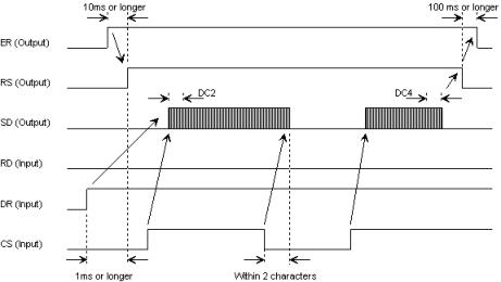
Timing Chart When The Fanuc NC Sends Data To
External Device.
1. NC outputs DC2.
2. NC outputs punch data in succession.
3. When data processing is delayed by the external
device, including the character currently being sent if
the CTS (CS) signal is turned off:
a) Data output stops within two characters
including the currently transmitted character when
CTS (CS) signal is input to the NC. When CTS (CS)
signal is turned on again, data transmission starts.
(Fig. A)
b) If the control code DC3 is input to the NC, the NC
will stop data output within ten characters. When
control code DC1 is input to the NC, the NC will start
sending data again. (Fig. B)

4. The NC starts sending the next data in the output
buffer if the CS signal is turned on after the external
device completes data processing.
5. NC issues DC4 upon completing data output.

ISO Tape Code Chart

EIA Tape Code Chart


Cable Information
